


 Date:2026.10.30
 Views: Loading


For energy storage utilities, the useful question is not how many protections appear in a list. It is whether cell materials, thermal control, isolation, alarms, suppression, and enclosure design form a coordinated chain in which one layer can still respond if another is challenged.
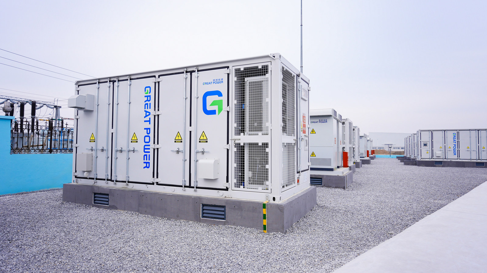
Safety Layers Start with Different Failure Scales
Cell materials establish the innermost safety boundary. Material stability and electrolyte behavior influence how a cell responds to heat, electrical abuse, and internal defects. At the cell level, LFP chemistry and flame-retardant electrolyte technology can contribute to the safety design, subject to validation in the relevant cell configuration.
Cell design cannot manage every external condition, but it sets the starting behavior before pack structures or cabinet systems become involved. A multi-level design first reduces the probability or severity of initiation. Equipment outside the cell then addresses hazards that move beyond that boundary.
The next boundary is the pack. Cells are connected closely enough that heat, pressure, or an electrical fault can reach adjacent units unless the structure interrupts that route. Our LiqPack design uses thermal insulation between cells and a thermally insulated metal casing to limit heat transfer. Its liquid-cooling system is specified to maintain cell temperature differences within 2 °C under the stated operating conditions..
Modular pack design also reduces short-circuit risk, while pressure-relief and thermal-insulation structures manage different consequences of an abnormal cell. These measures turn the pack into an active containment boundary inside the energy container.
Thermal Control Keeps Protective Margins Available
Temperature uniformity matters before an alarm occurs. Cells at different temperatures can age and respond differently under the same current, which makes operating limits harder to manage across a large system. Liquid cooling moves heat away from densely arranged cells and limits local gradients. The Max-20HC-6250 combines self-developed Ultra 588 Ah cells with high-safety liquid-cooled battery packs.
Thermal control does not replace isolation or suppression; it reduces the time that cells spend near conditions where those later layers may be called upon. Monitoring connects thermal behavior to operating action. A sensor must detect a meaningful change, the control system must interpret it, and an alarm must reach a defined recipient.
Automatic fire-alarm functions are included in our C&I safety architecture. Their practical value depends on priorities, shutdown logic, communications, and site response procedures remaining available. For energy storage utilities, that chain extends beyond the container wall because plant controls and operators need to know which unit is affected and what action the equipment has already taken.
Protection Zones Address Different Exposures
One enclosure can contain areas with very different exposure to water, dust, and electrical hazards. Protection is zoned in Max-20HC-5000. The pack carries IP67, the high-voltage box IP54, the electrical compartment IPX5, and the complete system IP55.
The ratings describe separate zones; they are not one universal property for the complete enclosure. Pack, enclosure, and component ratings remain valid only within the tested zones and configurations named by their evidence; crossing those boundaries creates an unsupported technical assumption.
Fire protection also changes with scale. Great Power's C&I architecture uses suppression inside the pack, gas suppression inside the cabinet, and water fire protection as three distinct levels. A pack event, a cabinet atmosphere, and a larger enclosure condition do not present the same access or propagation problem.
The three levels provide responses at successive physical boundaries. UL 9540A testing adds evidence about behavior in a defined configuration, while the project still has to confirm installation, detection, water supply, access, and emergency coordination. Electrical protection runs alongside the thermal chain.
Current, voltage, insulation, and communication abnormalities require distinct responses, including unit isolation. Energy storage utilities need those actions to remain selective so an affected block can be separated without creating loss across the plant. Coordination studies and commissioning then verify that local protection and external switchgear follow the intended sequence.
System Evidence Must Match the Installed Configuration
The Max-20HC-6250 features a six-layer safety protection system for liquid-cooled energy storage cabinets. Our Max-20HC-5000 references UL 9540A testing and NFPA 855 requirements, with their applicability subject to the relevant system configuration and project documentation.. These facts are most useful when tied to the exact model, cell, pack, cabinet arrangement, software version, and installation conditions being proposed.
A certificate or test reference cannot substitute for identifying where a barrier sits, which event it addresses, and how it communicates with the next layer. Maintenance preserves the separation among those layers. Cooling circuits, seals, sensors, alarms, pressure-relief paths, suppression equipment, and electrical isolation all require checks appropriate to their functions.
Changes in duty, software, layout, or nearby equipment may also alter the original risk assumptions. Great Power's safety design spans material and cell behavior, pack containment, thermal control, cabinet response, and enclosure protection. Failure scales across the energy container meet barriers whose integrity must survive operation, service, and routine maintenance.
 Consulting & Services

 Great Power
